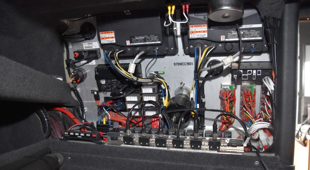
A good example of colour coded and easily identifiable wiring.
This article is intended to provide boat owners with a check list that can be kept in your chart table and when inspired to carry out some maintenance checks, pull out the list and go through some of the items and have your electrician carry out any repairs that you feel are necessary.
This article is not intended to be an exhaustive technical explanation of the Acts and Regulations that electrical inspectors and electricians refer to when carrying out inspections and electrical work on marinas and boats. Warrants of Electrical Fitness (WoEF) are required to be done and certified by your electrical inspector every four years. An electrician may carry out the required repairs, if any, but is not authorised to issue the WoEF certification. This certification normally comprises the inspectors report, the window sticker and accompanying certificate, the lead tag and the electrician’s certificate of compliance for any work done.
Any fixed electrical appliance, like inverters and battery chargers, forms part of the permanent electrical installation, certified through the WoEF process. Included in the WoEF certification is the a.c. and d.c. installation, batteries, earthing.
Your electrical inspector will carry out a visual inspection, together with testing with instruments to verify that the electrical installation complies with AS/NZS 3004.2:2008 and 2014 depending on the year your boats electrical installation was done. Compliance is not retrospective, however, your inspector, for safety reasons may recommend upgrades for your consideration to comply with the latest standards.
This check list, not in alphabetical order, will start off from the marina pedestal end, work its way through the a.c. installation, progress onto the d.c. installation and finishing up with the earthing.
Shore Supply Lead
The shore supply lead forms part of the installation wiring of the boat and is therefore required to be tagged at the time of the WoEF inspection and every 12 months thereafter by your electrical inspector.
Temporary Shore Power Leads
These are not required to be certified by an electrical inspector and do not form part of the WoEF certification. These leads can be tested and tagged by your electrician. Your lead is required to be weatherproof (IP56) throughout its length, including if it is unplugged at the boat end from the appliance inlet.
Important checks that can be done on the lead, is to ensure there is a weather proof seal on the lead plug at both ends, the securing ring is not missing or damaged in any way and there is a weather proof cap that can be closed off when the plug is removed from the boat end. The boats end appliance inlet is also to have a weather tight seal, securing ring and a cap when not in use.
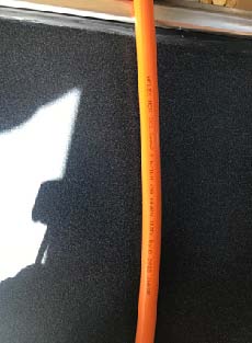
Also check that there are no knicks or chaffing on the outer sheath of the cable. The lead is required to have the following information clearly printed or embossed on the lead every 500mm, the manufacturers name, the lead conductor size of no less than 1.5 mm² and rated for heavy duty by indicating a voltage of 0.6/1000 volt.
The Main Switch
Very often found in the cockpit locker as close as practicably possible to the appliance inlet and comprises a residual current breaker with overload (RCBO), normally 16 or 32A housed in a weather proof enclosure and clearly labelled with “on” and “off” positions and “main shore power” and tested during the WoEF. This RCBO can sometimes be located on the main a.c. switchboard in the boat.
The table below gives a very good idea of the cross-sectional area of the lead conductors, size of the pedestal circuit breaker and the associated maximum lengths permitted.
A.C. Switchboards
The main a.c. switchboard, which is required to be “contained” to prevent or minimise the spread of fire, not have exposed live wires and bus bars within the switchboard with the cover open. There is to be no low voltage d.c. located in this switchboard. When opening an a.c. switchboard the earth and neutral bar are to be clearly visible and easily accessible for testing and maintenance.
Ship-off-Shore Selector Switches
These are mandatory for boats where there is more than one source of power supply onboard e.g. shore power, inverters and or generators. This is an important isolating and safety switch, to provide for an “off” position, to meet part of the requirements for back feed prevention from sources of electrical supply on board and that only one source of supply can be selected on the boat at any one time. As always there are exceptions to the rule, but not covered in this article.
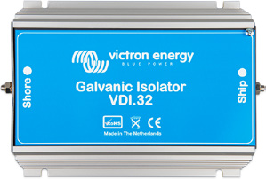
Galvanic Isolator
Also an important consideration, although not mandatory, is the galvanic isolator and is often highly recommended. The galvanic isolator is installed to minimise the adverse effects of galvanic corrosion.
Shore power lead with mandatory printing
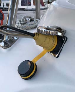
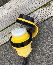
Vessel end plug inserted with IP56 cap.
Isolation Transformers
These and particularly the protection and earthing arrangements will be carefully considered by your electrical inspector during the WoEF. Isolation transformers add another layer of safety against electrical shock and also minimise the adverse effects of galvanic corrosion.
Reverse Polarity and Power Available
Important and mandatory requirements are the power available indicator and the reverse polarity trip mechanism with indication. The power available and reverse polarity indication on boats built before 2014 are not mandatory but recommended. It is mandatory for boats built after 2014 to be fitted with power available and reverse polarity automatic ripping mechanisms with indication. The reverse polarity automatic tripping mechanism is very often integrated with the main switch and tested during the WoEF.
D.C Switchboard
Similarly, the low voltage d.c. switchboard is to remain separated from any a.c. wiring, by way of conduits or insulating barriers. The a.c and low voltage d.c switchboards are to have a safety separation barrier between them if housed in the same area.
Ensure that all battery terminals are protected from falling metal objects and that batteries are housed in acid resistant boxes and secured with acid resistant brackets.
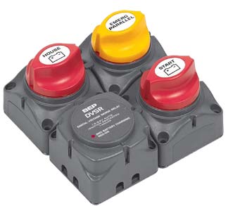
House Batteries
The house battery bank, consisting of one or more batteries are to be fitted with an easily accessible isolating switch external to the battery box and fitted with a fuse preferably external to the battery box. There are “sealed” type fuses, which can be very easily retrofitted that connect directly to the positive battery terminal if the fuse is to be in the battery box.
Start Batteries
Also consisting of one or more batteries, are to be fitted with an easily accessible isolating switch. Fuse protection on start battery banks is not mandatory, given the very high current (in Amps) that can be generated when starting your engines.
Pedestal end plug with rubber seal.
Battery Terminals
Ensure that all battery terminals are protected from falling metal objects and that batteries are housed in acid resistant boxes and secured with acid resistant brackets. A common practice is acid resistant rubber sheeting to be cable tied to the main battery cables covering the terminals. Fitting individual battery terminal covers can often be very cumbersome when there is more than one cable connected to the battery terminal, the rubber sheeting works well. For a more permanent installation, stainless steel threaded rod, fitted vertically at opposite ends of the battery bank, connected with a hard wood strut to hold down the battery and covered with a clear PVC sheet of around 4-5mm thick is ideal.
Emergency Parallel Switches
These are mandatory and used to join the house battery bank to the start battery bank when the start battery has failed to bring the engines to life.
Battery Box Ventilation
Since 2008 the regulations require a battery box containing lead acid or alkaline batteries to be well ventilated to free air, often consisting of a louvre at the base of the battery box and another louvre at the opposite end of the battery box above the battery terminals. This will allow the hydrogen and oxygen to rise into clear air and prevent the accumulation of these explosive charge gases. There is a requirement for forced ventilation if natural ventilation is not practical. Forced ventilation is to operate during battery charging and can be electrically interlocked with engine and or battery chargers.
Battery Chargers
Battery chargers should have protection against battery over voltage and battery bank discharge back through the charger output. They should also have charge current indication (in Amps) or charger output status, which could take on the form of bulk, absorption and float LED indication. Battery chargers should also conform to the applicable NZ Standards.
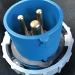
Vessel end plug showing non-compliant wiring colour.
Wind Generator and Photovoltaic Charge Regulators
In addition to the general battery charger requirements, the charge regulators shall be specifically designed for these systems. The regulators shall be adjustable to set the output voltage limit to suite the associated battery.
Generators
Generators shall have an alternative source for the starting circuit, typically a battery supply. A circuit breaker shall be fitted adjacent to the generator to protect the power cable sized for the maximum kW of the generator. The ship-offshore change-over switch shall also control the power supply from the generator.
Generators from 2kVA to 15kVA shall be fitted with a voltmeter and amp meter. It is recommended that a frequency meter is installed. Generators larger than 15kVA shall be fitted with a frequency meter.
Your electrical inspector will also check to see that the earthing of the neutral is in place, taking into account isolation transformers that may be present and the on board electrical system type.
Inverters and Inverter/Chargers
Most importantly with inverters and inverter/chargers is to provide isolation of the d.c. supply and a.c. output. This is best done when built with a toroidal isolation transformer designed to provide full galvanic isolation, i.e. there is no hard wired connection between the input and output of the inverter inverter/charger, protects against electrical shock and minimises, if not completely removes the adverse effects of galvanic corrosion from the associated circuits. Marine grade inverter inverter/chargers will be designed and built to provide full galvanic isolation to meet the required Standards. The a.c. output shall be protected by a suitably sized residual current breaker with overload (RCBO).
The inverter inverter/ charger shall have a voltmeter or indication at the main switchboard or in close proximity to the switchboard, to indicate whether or not it is switched on. A hazard warning label is also required, informing that the boat is equipped with an inverter.
The house battery bank, should be fitted with an easily accessible isolating switch external to the battery box.
Boat end plug showing weather proof IP56 cap.
Inverters and inverter/chargers shall be permanently installed to a permanent boat structure, away from heat sources, below fuel lines or above batteries. Output earthing and neutral connections will also be taken into account as previously mentioned under generators.
Earthing and Equipotential Bonding
Your inspector will check the earthing and equipotential bonding and advise on the condition and readings taken and whether remedial work is required. Good earthing and equipotential bonding will ensure the safety of folk using a.c. on board and minimise the adverse effects of galvanic corrosion to engines, prop shafts and props. Careful consideration should be given to the earthing systems when boats generate their own electrical power on board via inverters or generators and where isolation transformers are present.
Labelling
As the saying goes, the job is not done until the paperwork is complete. Apart from the WoEF paperwork, is the important aspect of labelling. Labelling should be done in such a way that any person on board with marine experience or not, is able to clearly understand the application of the label. Clear indication of on/off control of main a.c. and d.c switches will go a long way to reducing the potential chaos in times of emergency and/or operation in heavy rolling seas.
We trust that this article has shed some light on some of the important requirements for WoEF certification and wish you safe boating.
The galvanic isolator is installed to minimise the adverse effects of galvanic corrosion.