While you may understand the basic working functions of your marine diesel in your boat, have you every taken the time to appreciate how all that power gets into the water, so the thrust and performance is smoothly and somewhat vibration free as it is transferred to the propellers. A lot of focus goes in to reducing and containing noise and vibration within a vessel’s engine room so those same fundamentals should be applied to your selection of driveshaft componentry. When it comes to universal joints, you should install a high spec joint that features thrust washer inserts in the bearing caps. By removing the clearance required between the bearing journal end and cap these joints run cooler and quieter. Rilson-coated slip splines are also a good idea, as the fine tolerance combined with low friction properties of coated Euro series splines in marine shaft slip sections results in a very quiet, smooth running driveline even at high operating speeds. With smooth, coated splines maximum power can be transferred through the driveline rather than fighting against friction.

Another technical and safety benefit of the Rilson spline coating feature is electrical isolation between flanges. On the other hand a standard, coarser ‘metal-to-metal’ spline assembly will need regular lubrication and checking for spline wear to keep noise and general operation at acceptable levels. Similar to gears, uncoated splines can also produce annoying ‘chatter’ at low rpms. The use of Universal joint and CV shafts with their higher tolerance of misalignment compensates for engine mount sagging and reduces the need for costly alignment equipment.
Overcoming Space & Layout Restrictions
It is not often there’ll be an abundance of space left within a hull or engine/propulsion area to configure a bulky driveshaft. Any extra length or height required in your layout will encroach on available cabin or service area space. Modern marine drivelines are predominantly manufactured from appropriately rated ‘Euro’ series componentry which provides the strength and performance needed for these applications while being very dimensionally compact. For further space advantage confirm that the driveline manufacturer can machine end flanges to suit the gearbox fixings eliminating the adaptor plate. Engines are often positioned to balance out the weight of other plant and equipment so in some instances a longer series shaft may be needed with support bearings fitted at midpoint. In shaft drive vessels incorporating a thrust bearing unit in the driveline configuration can allow for a horizontal engine position which is ideal for better space utilisation as well as ease of installation and alignment. A New Zealand market leader in driveline technology, is Auckland based Beattys Driveline Technologies, who offer a wide range of driveline solutions, such as universal joints, coated slip splines, flywheel couplings and thrust bearings.
The company recently installed one of their Turret Marine drivelines into the Elite 20m Highlander, which according to the owner runs smooth and vibration free. The short-coupled cardan drive shafts along with TM150 thrust bearings, ensure power is transferred quietly with minimal vibration. The drive train is isolated from the engine with thrust bearings and universals to take the load off the engine mounts and transmit the thrust directly to the hull. Beattys motto is that drive shafts should be seen and not heard!
Dealing with Thrust
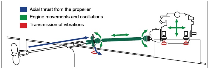
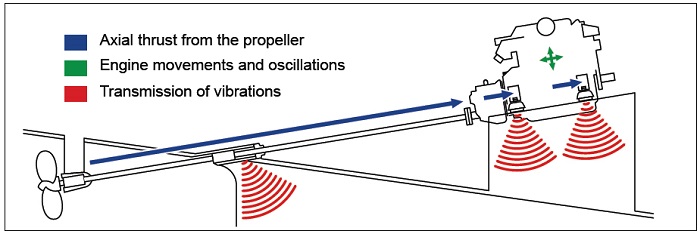
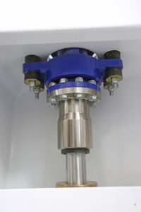
By combining thrust bearings with a marine Cardan or CV shaft you get the perfect solution for conventional shaft drive vessels, reducing noise and vibration and simplifying engine installation and shaft alignment. Thrust vibration is absorbed through rubber pads mounted parallel to the propeller shaft. Rubber performs better under compression, by incorporating these units to absorb all the thrust in the design, softer engine mount material can be used further enhancing the reduction of noise and vibration.
Without the absorption of thrust at the propeller end of the driveline you risk the transfer of thrust and shock to the gearbox that can be costly to repair if damage occurs. Attachment and fixing of these thrust bearing units is simple with an internal clamp design for shafts up to 2.5′ and larger bearings have standard flange bolting patterns. The ability of universal joints and CV joints to operate at considerably higher angle than other coupling designs compensates for hull and mount movement over time reducing vibration and load on the propeller shaft seal.
Mounts & Couplings
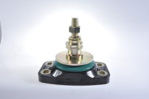
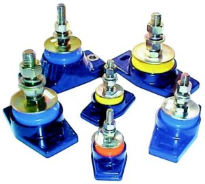
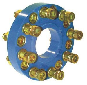
Let’s move forward to the engine end of things again. Your engine man, we presume, has sorted out the right gearbox ratio and has discussed rigid mounting versus resilient mounting options with you. Resilient mountings are necessary to reduce the transmission vibration. There are a number of brands available, such as from Australian manufacturer Polyflex. They offer over 1600 models (10-2000kg) of engine mount systems, which are moulded from heat cured polymer alloys and are both oil and fuel resistant. Then there is the gearboxes output flange and the decision is whether or not toinstall a flexible coupling between the gear boxes output flange and the propeller shaft’s companion or mating flange. Flexible couplings combined with a correctly selected mounting system allows the engine/gearbox to be vibration isolates from the hull and accept the thrust from the prop and shaft to move the craft through the water. It is preferable to ensure the mounting system incorporates a failsafe system and meets survey. The flexible coupling also dampens the torsional vibration coming from the engine and gearbox to the hull. It is essential to take on board the fact that while the name suggests that these couplings ‘flex’ and will therefore take care of at least some of any misalignment problems, this is not so, in fact they will accept very little in the way of misalignment. Sound engineering practice is to draw both flanges together without a flexible unit in place (make sure the shaft is located centrally in the shaft tube and not off centre). Refer to fitting instructions and retain instruction manual for future reference and maintenance. Should the flanges not be able to draw together, it is then required to fit a dummy or solid spacer between the flange faces to do correct alignment. Alignment is done by adjusting the engine brackets on the mounts. There should be no more than 3 thousandths of an inch discrepancy at all points around the circumference of the two mating flanges, and then to fit the flexible coupling.
What they will do however is effect a reduction in transmitted vibrations and assist in the reduction of the assorted squeals, rumbles and other disconcerting noises which propellers and drive lines can generate. There are several types of coupling on the market and again one of the most popular is from Polyflex, who produce a wide range of flexible disc couplings, designed to act as a dampener between the gearbox and driveshaft, while still maintaining strength, rigidity and performance. They have over 200 models suitable from 10 to 2500hp and are continually expanding their range. All their couplings as well as mounts are available with DNV Type Approval.
Strut & Shaft Science
The placement of the strut itself can have big bearing on things too. If it is located further away from the stern tube bearing in front of it than a distance equal to 4 times the diameter of the shaft, that shaft is likely to begin to behave like a skipping rope being swung between two vigorous girls. Similarly, allow more than one shaft diameter between the rear of your strut bearing and the front of your propeller boss and the prop becomes prone to wobble about like a limp wrist. This may all seem like a bit of a juggling act, but, if you don’t get this end of the business right to start with, no matter how light your hull, how fair its bottom, or how hairy-legged the horsepower you will be disappointed with its performance. The actual size of the prop shaft will depend on how much horsepower it is being asked to transmit and at what revs, and the prop man is the best guy to establish this, as there are materials of different tensile strengths to take into account.A good rule of thumb for pleasure craft is not to have your prop revolving any faster than 1500 revs per minute, nor the tips of the blades exceeding a speed of 10,800
feet per minute, so taking our theoretical 300 hp at 2,400 rpm engine, if we want our prop to turn at 1,500 rpm we are looking at a 1.6:1 ratio. It is probable that there is no such ratio commercially available, so you would have to settle on the nearest to it. If a 1.8 is all that is available, we will need to swing roughly a 25 1/4 inch prop
Keeping the Water Out
And now to one of the most important decisions as far as keeping the ocean outside your boat is concerned. The point where the propeller shaft penetrates the hull and enters the ocean is still frequently referred to as ‘stuffing box’
because the traditional seal consisted of several layers of greasy gland packing or ‘stuffing’ wrapped around the shaft and compressed by a collar and two tightening screws. In the same housing was usually a white metal bearing to support the shaft. These admiralty type stuffing boxes are still commonly used but have several minor drawbacks in that they have to be adjusted reasonably frequently. If you squeeze them too tight they heat up and can mark the shaft; to get them too loose and they dribble. They usually have a grease nipple or grease cup on them to take care of any friction, but even so it was usually necessary to set them so that they dripped occasionally just to be sure that some water cooling was getting to the hot spot. The result was always a puddle of greasy water in the bilge and a mathematically correct circle of the same brew centrifuged onto whatever happened to be in the line of fire.
Currently you have a choice of three different types of seal on the seam the first being a ‘face to face’ seal. This involves a ceramic or carbon face mounted on the portion of the device attached to the hull and a mating face clamped to the propeller shaft and exerting mild pressure on the mating surfaces by means of a rubber bellows also clamped to the shaft. This is usually cooled by a by-pass line from the engines salt water cooling unit. This system works extremely well even if the shaft bearings should get a little sloppy and allow the shaft to move about a bit. There is one distinct disadvantage, however, if the rubber bellows should ‘loose its memory’ or slack off a bit, it can be slid further down the shaft to increase the pressure on the mating faces. This is fine if the engine’s resilient mounts are fairly rigid, but if they have got a bit tired or are soft enough to allow the engine to move forward as the prop thrust increases, the bellows move forward as well, allowing a gap to open up between the mating faces of the seal – and the water fairly hoses in. The fact that the clearances around the shaft are too small to allow you to jam anything into them doesn’t help either. This potential problem has been got around by several manufacturers who have used modified ‘lip seals’. These are a rubber or synthetic ring encircling the shaft with a stainless steel coil spring behind them exerting gentle pressure and squeezing a V shaped section onto the shaft. Thus the shaft is free to slidebackwards and forwards without the seal leaking or being damaged. From here on back some vessels have a stern tube with a shaft-supporting bearing at its rear end; some just leave the shaft unsupported and allow water to flow in as far as the stuffing box seal. The thickness of the shaft, and its unsupported length usually decide which method is used.
If a rear stern bearing is required the type of material employed is frequently the same as that used in the strut bearing and this can be one of several types. The old style ‘Noveasteen’ or ferobestos type hard materials have been almost completely superseded by soft or self lubricating materials such as Novasteen, Johnson Cutless rubber lined, Thorndon, and, Visconite, the latter two being synthetic material. These synthetic materials not only have a higher load carrying capacity than white metal or phosphor bronze, they are easily machined, hold their shape, but also have a very low friction component and combine with water to form an efficient lubricant.And now we are back to the propeller – the end of the line, and the bottom line too, as far as your boat’s performance is concerned. Propping never has and never will be a precise science – there are too many variables. But with a little help and using common sense in the selection and sizing process you should end up with the right combination. However, never underestimate the importance of getting the rest of the drive train right. It will pay dividends in the end.